Embedded - Reddit
28 February 2024 00:15
firmware editing
hi so ive bought a controller from AliExpress its easysmx T39 and when i connect it over Bluetooth its only broadcast as pro controller aka Nintendo switch but ive got this project idea to edit it firmware and make it broadcast as an official xbox wireless controller im at below noob in programming so helppp
https://redd.it/1b1px6c
@
Читать полностью…
Embedded - Reddit
27 February 2024 22:15
Germany or Canada ? ( embedded job market )
Like the title suggests, wanted to get the opinion of recruiters, industry veterans and fellow professionals about the job prospects and salary expectations for early to mid career in embedded firmware development jobs in Canada and Germany. How would one select which country to work in?
Hoping to keep the conversation focused on Opportunities, salaries and career growth.
https://redd.it/1b1luqx
@
Читать полностью…
Embedded - Reddit
27 February 2024 20:15
QSPI using LPSPI in i.MX RT1060
Why am i receiving data in RX buffer while transmitting data over LPSPI in 4-bit mode in RT1060. I am aware that RX and TX masking can be used to overcome this but why would the RX buffer be filling even though it is a half duplex communication?
I am supposed to receive device id of 2Bytes from the QSPI flash once the command set required by flash is transmitted by the MCU, but when I’m reading the array after getting interrupt for RX, it is filled with 0xCC.
Could it be related to wrong RX buffer watermark?
Any suggestion is highly appreciated.
https://redd.it/1b1k656
@
Читать полностью…
Embedded - Reddit
27 February 2024 18:15
Statements of Support for Software Measurability and Memory Safety | ONCD | The White House
https://www.whitehouse.gov/oncd/briefing-room/2024/02/26/memory-safety-statements-of-support/
https://redd.it/1b1g7zu
@
Читать полностью…
Embedded - Reddit
27 February 2024 16:15
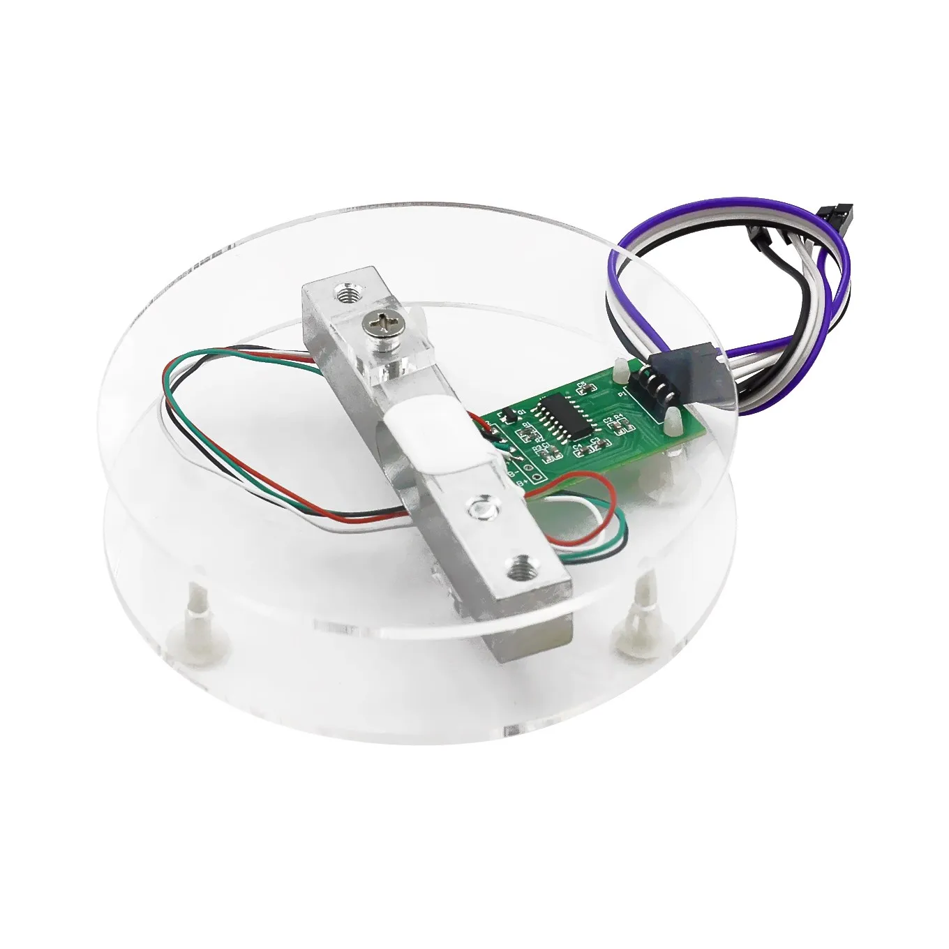
Is this the right setup for a beam load cell?
Does this look correct (I bought something similar to this).
https://preview.redd.it/qb1opxowj4lc1.png?width=1482&format=png&auto=webp&s=f701cfbaed281c7db58eaf44de53654120bca5db
One of the little rectangles isn't on the edge of the load cell. If I put it on the edge, the round platforms won't be aligned.
Note: I'm using a HX711 amplifier.
https://redd.it/1b1b732
@
Читать полностью…
Embedded - Reddit
27 February 2024 14:15
External monitor on Kria KR-260
Hello, I want to connect my kria kr-260 board to an external monitor and show the output of my project in it. What steps should I follow?
https://redd.it/1b1bbv7
@
Читать полностью…
Embedded - Reddit
27 February 2024 12:15
How to create connection to XBP9X-DMUS-001
Hello,
I am trying to develop a custom telemetry module using XBP9X-DMUS-001. I am planning to connect this module to STM32F407 to recieve data and send the data to computer using uart to usb driver. But the question is, i need to create a seperate connection for XBP9X-DMUS-001 to program the component.
I contacted to Didi to request an example scheamtic of the chip. In the schematic they used FT4232HL (USB to UART driver, Quad channels). I am thinking to use two separate uart connection one for usb connection to computer and the other one is for programming to XBP9X-DMUS-001.
I ask for your help to enlighten me. Unfortunately, I don't have a huge budget and if I make a mistake, I may have to wait a long time to get the RF module rebuilt. Therefore, I would be very happy if you could help me with this issue and tell me how I can solve this problem.
The example schematic link: https://hub.digi.com/dp/path=/support/asset/xbee-pro-sx-development-board-schematic/
The module's datasheet: https://www.digi.com/resources/documentation/digidocs/pdfs/90001477.pdf?src-supplier=Digikey
https://redd.it/1b190s6
@
Читать полностью…
Embedded - Reddit
27 February 2024 09:15
Developer friendly dev boards for BLE Mesh provisioner
I have been working on creating an embedded provisioner using STM32WB55RG but I feel as if there is not enough flexibility to use it as an BLE mesh embedded provisioner. What are some good boards for creating a mesh network along with an embedded provisioner and not a mobile app to do provisioning?
https://redd.it/1b15wsa
@
Читать полностью…
Embedded - Reddit
27 February 2024 07:15
Masters application
Hi All, I’m currently working in a semiconductor company (<1yr). I joined this company as a fresher and from then started to like this embedded software development domain. I am interested in developing drivers for blocks, firmware, developing kernel code. Could you guys suggest me some masters degree that would align with my interests?
https://redd.it/1b14sty
@
Читать полностью…
Embedded - Reddit
27 February 2024 04:15
What does the factory flashing / recovery flashing look like?
Assuming (and simplifing) that we talk about Linux capable SoC, which has an eMMC or NOR flash on board, how one can perform initial flashing or reflash a stroage when the processor is not able to leave a boot ROM due e.g. corrupted eMMC or NOR flash memory? I suppose that it could be done using jtag, but what the other options are on the table? In general - because I guess it varies from vendor to vendor. Does boot ROM usually have such a capability that allows to reflash memories using eg. serial console?
https://redd.it/1b0ul5e
@
Читать полностью…
Embedded - Reddit
27 February 2024 02:15
CAN BUS Message Issue Transmiting with Teensy 4.1 and BAMOCAR d3 controller using FlexCAN_T4
Hello! I am trying to work with the CAN Bus protocol for a formula student team. We are using [teensy 4.1](https://www.pjrc.com/store/teensy41.html) as the master attached to CAN tranceiver [ISO1050](https://www.ti.com/lit/ds/symlink/iso1050.pdf?ts=1708671031307&ref_url=https%253A%252F%252Fwww.ti.com%252Fproduct%252FISO1050) and the [BAMOCAR d3](https://www.unitek-industrie-elektronik.de/images/pdf/BAMOCAR%20Digital/BAMOCAR-PG-D3-700-400_EN.pdf) controller as the slave. More specifically we are trying to send to the controller a command for the torque control. The COB ID of BAMOCAR d3 is 0x201 for receiving and the length of the message should be 3 bytes. Also in the code i use the FlexCAN\_T4 library so I do not have to specify the RX/TX pins of teensy 4.1 (as far as i have connected teensy's CAN1 which are pins 22 and 23). However, when scoping the CANH/CANL of the trenceiver it seems like there are no data being transmitted. All the connections between teensy and the tranceiver seem correct so I suppose there is an isuue with the code I have attached down below. I will appreciate your help and excuse me for any profound mistakes!
#include <FlexCAN_T4.h>
FlexCAN_T4<CAN1, RX_SIZE_256, TX_SIZE_16> can1;
void setup() {
Serial.begin(9600);
while (!Serial);
can1.begin();
can1.setBaudRate(500000); // 500kbps baud rate
}
void loop() {
CAN_message_t msgTransmit;
msgTransmit.id = 0x201; // receive address COB ID
msgTransmit.len = 3; // DLC
msgTransmit.buf[0] = 0x90; // torque register
// Set torque command value to 50%
int16_t torqueValue = 16380; // 50% of maximum torque
// Little Endian format
msgTransmit.buf[1] = torqueValue >> 8; // Low byte
msgTransmit.buf[2] = torqueValue & 0xFF; // High byte
can1.write(msgTransmit);
delay(100);
}
​
https://redd.it/1b0vk9o
@
Читать полностью…
Embedded - Reddit
27 February 2024 00:15
Can someone help me understand the current capacity of a CR2032 and how it applies to my application? I think I know the answer, but just need a second opinion.
This is going to be hilariously easy for some of you and I apologize if this is the wrong subreddit.
I have a small IoT device that uses a RYLR998 LoRa module (datasheet) that I'm powering with an Energizer CR2032 battery (datasheet). When the device sends a transmission I often get a CRC error; when I plug the device into a 3v power source I never get the CRC error. I've connected a multimeter to the device and I can see that the voltage drops during transmission, I believe the current also drops since my status LED dims. This leads me to believe that my error is with the battery itself.
The datasheet of my LoRa module says it needs 140 mA to transmit and the battery says it can support 235mAh. Googling around, it appears seems like the consensus is that a CR2032 can really only support a current draw of 100ish mA. My assumption is that I'm not able to pull enough current from the battery to send a complete LoRa message.
Can someone help confirm that the the battery is insufficient to support this module? Is my line of thought correct or am I completely off?
https://redd.it/1b0vvv0
@
Читать полностью…
Embedded - Reddit
26 February 2024 22:15
FreeRTOS tasks get executed ONLY when a certain set of events occur
I am working on a code base which uses a Pub-Sub architecture and there is an event broker. A task needs to subscribe to some events and whenever those events occur, the task gets executed. All of this is implemented using FreeRTOS.
I was under the impression that every task that gets created is executed always. But here due to the architecture, it gets executed only when an event to which the task has subscribed to is POSTED (Published).
How is this done? Of course I can read the code, but I would appreciate if someone can give me an overview of how this is done. Also is it a common practice to implement Pub-Sub architecture using FreeRTOS?
https://redd.it/1b0nhmo
@
Читать полностью…
Embedded - Reddit
26 February 2024 20:15
What are folks using for sensor data logging?
I have a radar (small, 60Ghz industrial sensor) outputting 3D position and velocity of multiple objects at 30Hz. I want to save this data in order to do some analysis and visualization in Python.
I am thinking that capturing the USB-UART serial output using a library like DuckDB or Polars would be sufficient. The TI board does some processing on the chip itself so this data is not raw, but already processed. The goal of tracking objects in motion means I need to keep the latency between the moment of observation and arrival of that observation to my computer as low as possible. I will eventually need to process this data and perform several actions in under 1.5s. The future integration plan is to move this project to run entirely on an MCU or SBC, with all of the attached sensors and servos in one system.
I'd like to strive for the most 'correct' way of doing this. I am hoping this project might open up new career avenues, and I'd like to learn/incorporate standard ways of doing things in this field. I have a PhD in climate science, but no formal training in the embedded world.
Thanks!
https://redd.it/1b0pvuw
@
Читать полностью…
Embedded - Reddit
26 February 2024 18:15
ARM features
I want a good book for ARM assembly and also talking about all the features such as privileged mode and memory management and all the features that an OS needs.
https://redd.it/1b0lneo
@
Читать полностью…
Embedded - Reddit
27 February 2024 23:15
I will be graduating in summer and I am actively looking for full time roles. If you were a hiring manager, would you give me a chance for an interview.
https://redd.it/1b1oq6q
@
Читать полностью…
Embedded - Reddit
27 February 2024 21:15
A way to read can messages
I have an ecu that sends and receive can messages ,is there a way to read them ?
https://redd.it/1b1la99
@
Читать полностью…
Embedded - Reddit
27 February 2024 19:15
My dream MCU that's probably never going to exist
I've been doing embedded designs with FPGAs and microcontrollers for... probably close to 15 years by this point, and have come up with a pretty solid list of things I like and don't like. But so far nobody has managed to put them all in a single chip which really annoys me. I can get my work done but it often involves adding extra chips for a job that really should be doable in one, or just being awkward for layout.
I've seen lots of stuff get *close* but never tick all the boxes.
Without further ado, here's the dream:
Midrange to high end embedded MCU class processor (Cortex-M4/M7 or so). Not a fancy 64-bit apps processor that needs external DDR and Linux and a dedicated PMIC, something with a few hundred kB of on die sram and flash that I can just dump a binary onto without any additional support ICs.
Available in a large-ish pitch BGA that is decently dense, but can be routed without microvias. 1mm or 0.8mm full array, or maybe 0.65mm with depopulated center for vias. No giant 144-TQFPs, no WLCSP (although it's fine if you *also* offer those for folks who need extreme density). There's a happy medium. Something along the lines of the STM32H7 176+25 BGA or the Xilinx 7 series FTG256 package.
FPGA-style IO pad ring (4+ banks with separate VCCIO for each, so I can interface with 1.8, 2.5, or 3.3V logic simultaneously without external level shifters). This implies reasonable grouping of peripherals to IO ports, and individual IO ports grouped contiguously on die/package (looking at you ST)
All the usual higher end MCU peripherals (crypto accelerator, RNG, Ethernet, quad SPI, etc)
Bonus points if it's got substrate bypass capacitance to simplify the PCB
Bonus points if there's a few kLUTs of FPGA for implementing weird IO protocols or offloading realtime functionality from the CPU
Basically take the package and pad ring of a FTG256 packaged Artix-7 FPGA and slap the guts of a STM32H7 inside. If you keep a bit of the FPGA fabric too, so much the better.
I've seen things that get close-ish but never quite there.
Some newer STM32s have like one 10-pin IO port on a separate power domain. Good start, but doesn't go far enough.
Xilinx's Zynq is way too big and complicated, and doesn't have any on die flash. Way too complex to use bare metal. I don't want to have to route a DDR3 RAM interface or mess around with building a Linux kernel and configuring u-boot just to get a bit of embedded control work done.
What do you folks think... anybody else wishing this existed? Is there a part that does this that I'm not familiar with?
https://redd.it/1b1i8tr
@
Читать полностью…
Embedded - Reddit
27 February 2024 17:15
Why shorten variable nums, eg. frmw instead of framewidth?
Are there valid reasons to do it such as this? The thing that's goofy to me, at least in the file that I'm looking at, is there's then a comment next to it that says /* frame width */
​
This is only one example, and might not have a compelling argument for short names, but in general, why shorten variables/function names in such a way in 2024?
​
Is this some remnant of the past when there were real reasons to shorten things so much?
https://redd.it/1b1f9eg
@
Читать полностью…
Embedded - Reddit
27 February 2024 15:15
How to properly work with patches in Yocto?
Hi,
I want to create custom device tree for my SoM. I am using Yocto and manufacturer's Linux kernel and I am wondering how should I handle it and not make a mess?
Imagine that first thing I want to do is to add just a basic device tree for my SoM. So I add a device tree, create a patch and include it in the Kernel's recipe .bbappend file. Then I add a first device to my newly created device tree, so I create another patch. I repeat the process for the next device. So far I have 3 patches and each of them adds one device, but it turns out that I have to fix some device-tree properties related to the first device I added, so I create another patch. Do you see where this is going? Imagine that I have 20 devices and at the end of the day when I have to fix some of them I will end up with dozens of patches. Is there any better way to handle it? I could imagine that in order to add 20 devices to my device tree the best solution would be to have a separate patch for each device regardless of the amout of changes I have made it the meantime.
https://redd.it/1b1br1b
@
Читать полностью…
Embedded - Reddit
27 February 2024 13:15
Confused where to find documentation
Hi all,
I would like to use this Infineon EVAL-M3-302F controller board to control a driver board. The reason is because this chip has an ARM Cortex M0 based microcontroller inside.
Now I'm having trouble finding documentation for programming the MCU. In the datasheet it says I need the following:
\- Arm Keil MDK
\- μVision® IDE
\- Infineon IMC300A DFP
Instead of using µVision I will use the Keil extension on VSCode.
But I don't find any documentation about the programming and the syntax...
Could anybody lead me in the right direction please?
Thanks in advance!
https://redd.it/1b1acas
@
Читать полностью…
Embedded - Reddit
27 February 2024 10:15
SPI transmission error with LSM6DSL(accelerometer).
The first spi transmit and receive reads wrong value of WHO_AM_I register but from 2nd transmission it reads correct value. Any reason why this might be happening? I am a beginner.
here is the code snippet
HALGPIOWritePin(GPIOB,GPIOPIN12, GPIOPINSET);
HALDelay(100);
send = 0x0f|0x80;
data = 0;
HALGPIOWritePin(GPIOB,GPIOPIN12, GPIOPINRESET);
HALDelay(20);
HALSPITransmit(&hspi2, &send, 1, 50);
HALSPIReceive(&hspi2, &data, 1, 50);
HALGPIOWritePin(GPIOB,GPIOPIN12, GPIOPINSET);
HALDelay(20);
but the following works
HALGPIOWritePin(GPIOB,GPIOPIN12, GPIOPINSET);
HALDelay(100);
send = 0x0f|0x80;
data = 0;
HALGPIOWritePin(GPIOB,GPIOPIN12, GPIOPINRESET);
HALDelay(20);
HALSPITransmit(&hspi2, &send, 1, 50);
HALSPIReceive(&hspi2, &data, 1, 50);
HALGPIOWritePin(GPIOB,GPIOPIN12, GPIOPINSET);
HALDelay(20);
HALGPIOWritePin(GPIOB,GPIOPIN12, GPIOPINRESET);
HALDelay(20);
HALSPITransmit(&hspi2, &send, 1, 50);
HALSPIReceive(&hspi2, &data, 1, 50);
HALGPIOWritePin(GPIOB,GPIOPIN12, GPIOPINSET);
HALDelay(20);
​
https://redd.it/1b15ke4
@
Читать полностью…
Embedded - Reddit
27 February 2024 08:15
Tag-Connect or similar with SWD and serial lines for STLINK v3?
As the ST Link v3 seems to contain VCP (two even?) it’s getting interesting combining it with Tag Connect or similar solutions so that once plugged in you get SWD and serial port all at once.
Are there any such solutions out there? What is your favorite connector for SWD on PCB suitable for both development and production?
https://redd.it/1b152si
@
Читать полностью…
Embedded - Reddit
27 February 2024 06:15
How do I mount a MIPI camera on a board that supports MIPI D-PHY RX 4Lane?
Hi. I am investigating whether the VC MIPI Camera Module is compatible with the Orange Pi 5.
The camera vendor provides FPC cables of 15 pin or 22 pin for CPU side. However, it looks like the Orange Pi 5's camera port does not connect to this FPC cable.
Can't I use that camera on the Orange Pi 5 board? If possible, which module should I purchase?
I am an inexperienced with hardware, so please forgive me if it seems like a stupid question.
https://redd.it/1b13jai
@
Читать полностью…
Embedded - Reddit
27 February 2024 03:15
Speed-testing a LWIP stack?
Good day everyone,
I have brought up a LWIP stack on a STM32H743 microcontroller which is connected to a UG96 module which provides internet access over a 3G cellular network. I have tested the connection by sending some data on a socket and was able to confirm that the connection works.
What I want to do now is to test the speed of this connection. If I had a command line I could've used iperf3, but all I have is a lwip stack on a microcontroller. Is there any standard way to test the speed of my connection?
Of course I can open a socket on an external VPS and try uploading and downloading a large amount of data from that and time it by hand, but I decided to leave that as the last option and ask if a more standard way for this problem exists in the industry.
Thanks for your time
https://redd.it/1b0v543
@
Читать полностью…
Embedded - Reddit
27 February 2024 01:15
Looking for a good way to keep code documentation and reference documents in sync.
I use a lot of technical documents, usually PDFs, as reference when writing code. Things like datasheets, project specs, wiring diagrams, etc.
I like to put a lot of information in my code so that someone looking at the code can understand the code and the system/environment that it runs in because I'm a firm believer in understanding the whole system when developing code for said system.
Right now I do that by writing verbose comments and putting references and links into my code. One problem with doing this is that the reader is continually going back and forth between reference documents and the code itself. The other issue is that if the reference document changes the reference in the code is no longer correct.
How do other people handle this sort of thing ?
I think it would be really nice if code files (*.c, *.cpp, *.h ) could contain images, clickable URLs, etc. I'm kinda surprised these files are still static text.
I think that Jupyter notebook is a step in the right direction in as much as it allows a developer to intermix code and documentation. It makes both the project and the code so much more readable and easy to understand.
The project isn't done until it is thoroughly documented. An hour of documentation can save days of work later trying to decipher why something was done a certain way.
​
​
​
https://redd.it/1b0w6ag
@
Читать полностью…
Embedded - Reddit
26 February 2024 23:15
Location sensors
Hey community
I would like to determine a location of a figure (fit I hand) on the (not more than a regular office table) surface ie when somebody moves that figure from (x,y) to (x1,y1), I would like to estimate that latter coordinate or the movement distance
I see couple of options in terms of the sensor type: time of flight and combination of magnetometer and gyroscope.
Time of flight censor is really strait forward to use except that there would a need to have a wall around the surface
Magnetometer and gyroscope would give me a direction and detection if movement was started. Given the average hand movement speed, I can estimate the possible movement distance. However, it is not that accurate since I need to know the velocity of the move.
Based on, I am wondering, what are another alternatives to consider?
https://redd.it/1b0twpv
@
Читать полностью…
Embedded - Reddit
26 February 2024 21:15
Can bus error on stm board
How to solve ack error in can bus operating in normal mode ?
https://redd.it/1b0q4yk
@
Читать полностью…
Embedded - Reddit
26 February 2024 19:15
ESP32-C3 + HX711 + load cell only display 0.0
I managed to get my ESP32-C3 and HX711 to run without errors with [this](https://gist.github.com/weiying-chen/b9da9eb8d8bd81a33a592f05226a15e2) Rust code. However, it only displays 0.0 even if I apply pressure on the load cell (the metallic rectangle).
I (29566) rust_esp32_hx711: Last Reading = Ok(0.0)
I (30566) rust_esp32_hx711: Last Reading = Ok(0.0)
I (31566) rust_esp32_hx711: Last Reading = Ok(0.0)
Very rarely, I see this:
I (10566) rust_esp32_hx711: Last Reading = Ok(7340032.0)
I (12566) rust_esp32_hx711: Last Reading = Ok(8388607.0)
And this:
I (8566) rust_esp32_hx711: Last Reading = Ok(63.0)
But then goes back to 0.0.
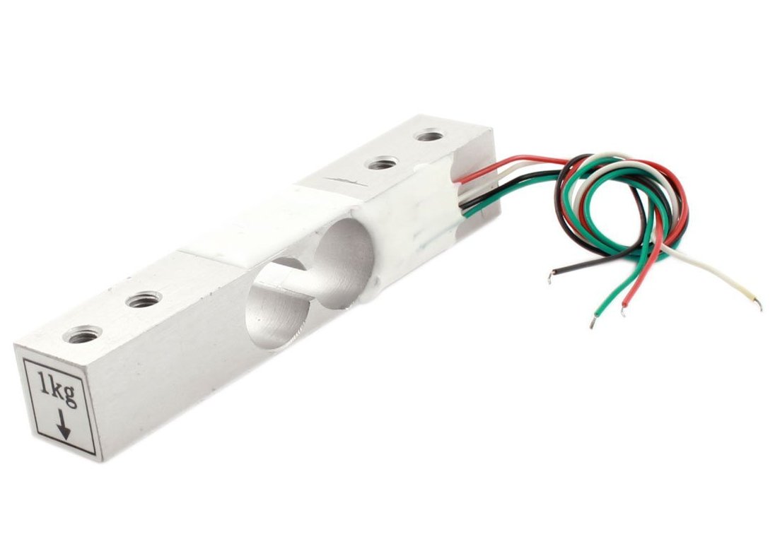
Maybe I'm supposed to attach [these](https://ae01.alicdn.com/kf/S49436f86b5fe417292587c7f628281a6R/Load-Cell-1KG-5KG-10KG-20KG-HX711-AD-Module-Weight-Sensor-Electronic-Scale-Aluminum-Alloy-Weighing.jpg) round things to the load sensor to see changes? This is how my setup looks like:
https://preview.redd.it/x7t0aaytwxkc1.png?width=1126&format=png&auto=webp&s=57ddba3ffa615b8f3eb034e7f957d19023006f61
I soldered the load cell's wires with jumper wires so I could connect it to the breadboard. (Maybe I shouldn't have done that?)
https://preview.redd.it/hrwawbwtxxkc1.png?width=738&format=png&auto=webp&s=8ec50e535792836343a038f8fed2de34efba135d
Notes:
* [This](https://shoplineimg.com/6486dbe2afaddb00694ea79f/64e20f002033b000013f537f/800x.jpg) is the HX711 I'm using.
* [This](https://hub360.com.ng/wp-content/uploads/2019/03/1kg.jpg) is the load cell.
* I checked the connections multiple times. Everything seems connected correctly, like [this](https://lh5.googleusercontent.com/TBcJN86DBlgeN23_v8S_dl2Rk8IY2MUPQMjkAnQs4ANHYnYii-gd3jVq2mGDWSC45dWX0nw3qXXsZb5EvtTPYsGL4ZcRbwOYAg_AOHZbXNlcSw224HOtBwkStRmAPH1JbCqCleWB).
https://redd.it/1b0izld
@
Читать полностью…
Embedded - Reddit
26 February 2024 17:15
MCU for Graphics
TLDR: need MCU recommendation for converting 10MB image to 720p video while rotating and displaying it.
I am building a device that needs to take an image of 1-10MB stored on some kind of external memory, and output it to a display (around 1280x720p or less) while rotating the it. The rotation should appear smooth (30-60fps).
Which MCU can handle this kind of a workload? I was considering the STM32U5F9 since it has a graphics accelerator, high speed memory interfaces, and MIPI DSI for display.
Would this work? Since this is a first prototype, I would like to prioritize having more resources than less, and ease of programming.
Looking forward to hearing your opinion, and would appreciate any advice.
https://redd.it/1b0kbml
@
Читать полностью…


 11